Dual-Flywheel Tennis Ball Launcher
Summer 2026
Role
Quinn Morris
Solo build: mechanical, electrical, firmware
Description
A battery-powered ball launcher with two counter-rotating flywheels, a stepper-driven lead screw for launch angle, and a phone app that runs the whole thing over Bluetooth. Built over summer 2026: mechanical assembly, custom electronics, and ESP32 firmware.
Overview
Background
Second attempt at a project I first built in 2023. That one ran on scooter wheels epoxied to their shafts and off-the-shelf speed controllers. This version replaces all of it: a proper flywheel drivetrain, motor drivers and microcontroller control, a linear actuator to control tilt, and a phone app to run it all.
Build
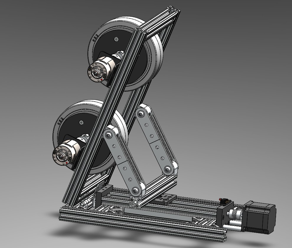
Two 6" × 2" rubber flywheels spin in opposite directions, each on its own RS-775 motor through a BTS7960 H-bridge. Running them at different speeds creates topspin or backspin, removing need for extra hardware. A T8 lead screw and linkage set the launch angle, with a limit switch at the bottom of travel so the ESP32 knows where it is on startup. Everything runs off a 12V 20Ah LiFePO4 pack through a buck converter, with fused channels and a voltage divider that reports battery level back to the app.
Result
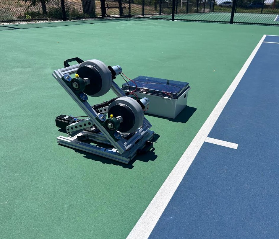
At 50% throttle and a 25° angle it clears a full tennis court, about 78 ft. At full throttle it goes past 100 ft. From that it is assumed the exit velocity is around 15–25 m/s. The tilt holds any angle with the motor off, and one charge covers a 60 to 90 minute session. Cost so far is about $500.
Development stages
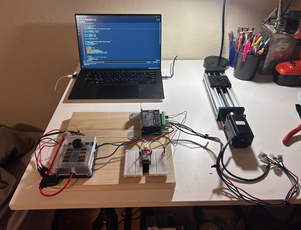
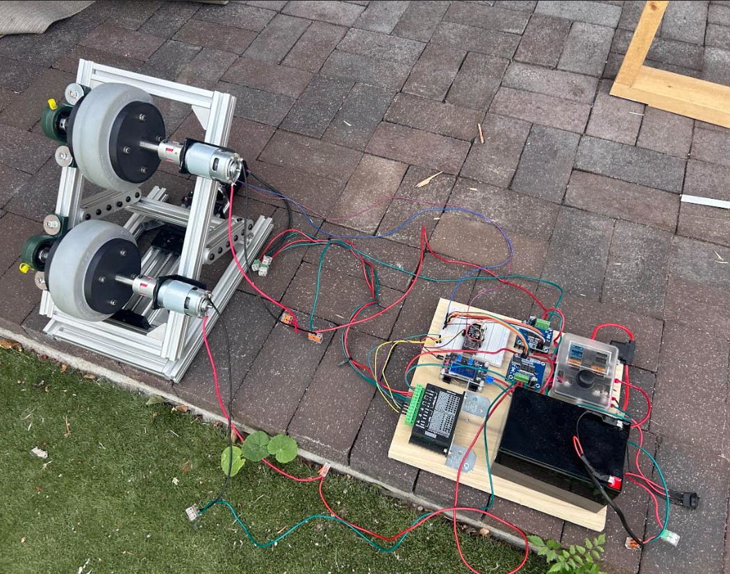
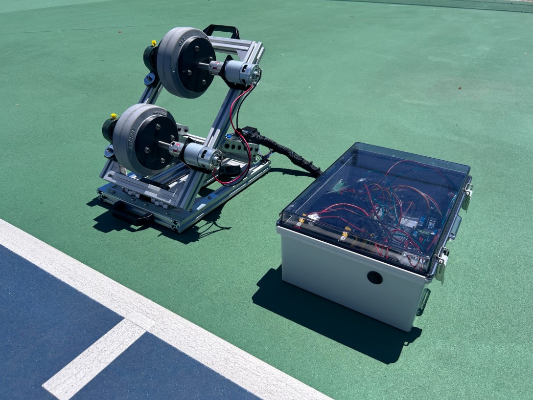
Many mechanical revisions and firmware iterations took place. Each pass atempted to reduce the ammount of wire clutter and really just make the machine easier to modify and transport.
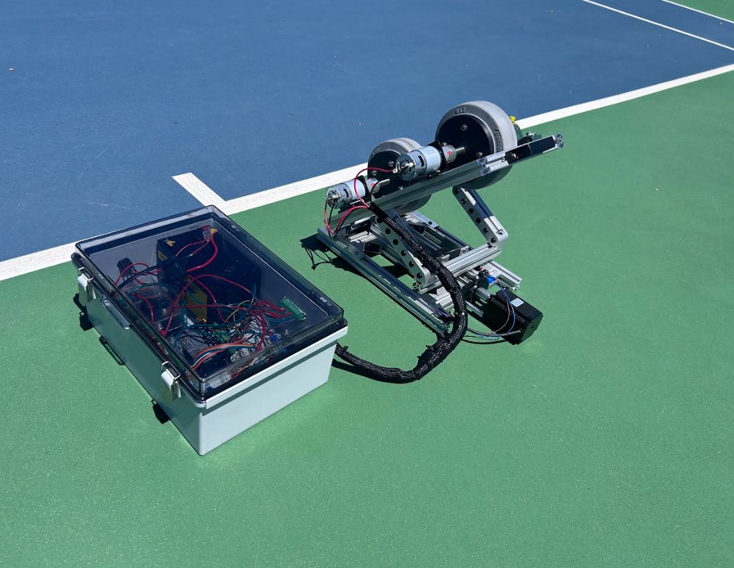
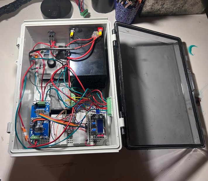
The first version had the ESP32, drivers, and buck converter screwed to a bare wood board with jumper wires everywhere. Moving the machine required unplugging many wires one at a time. Everything now lives in a sealed ABS box with one rocker switch and one quick-release connector, so setup is only two steps.
Flywheel drivetrain
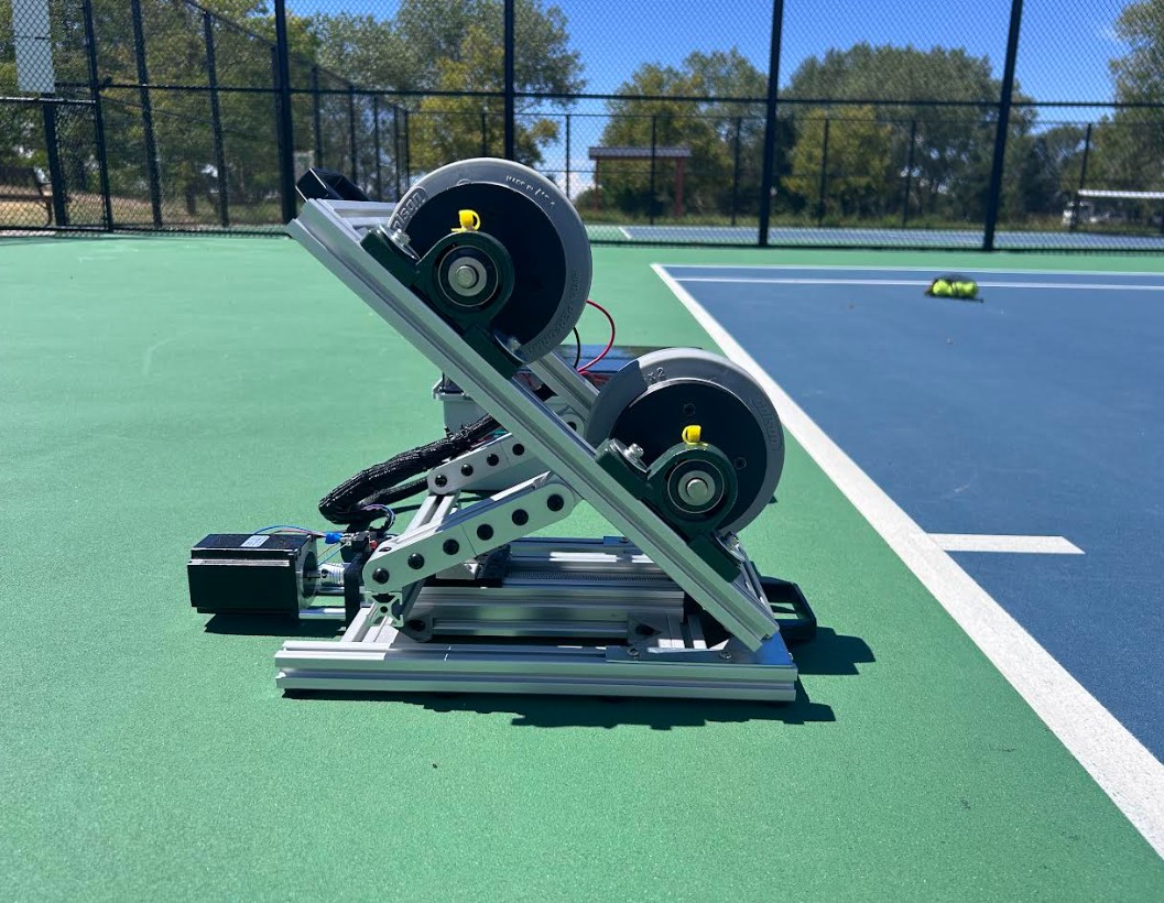
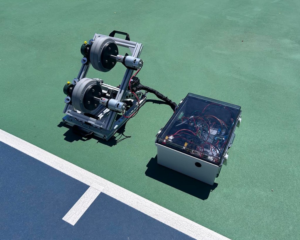
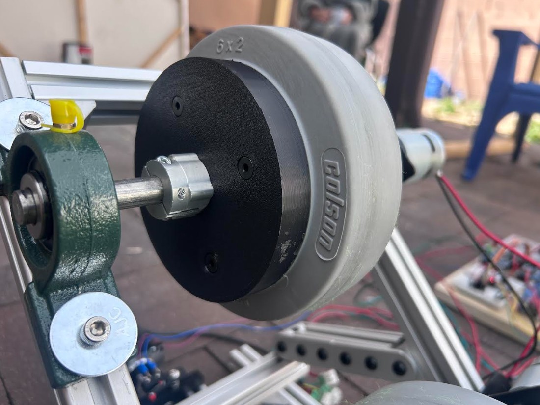
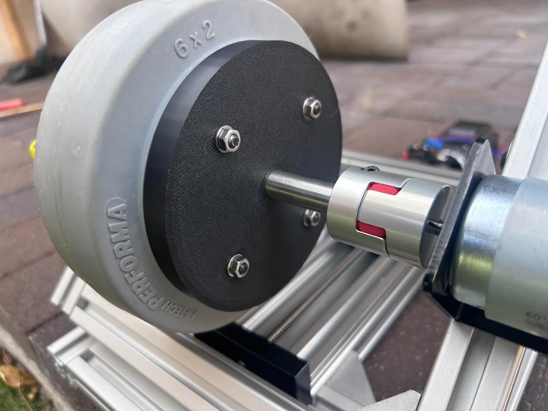
Two 6" × 2" rubber wheels counter-rotate to grip the ball and throw it. Each one has its own motor, so spin comes from simply running one faster than the other.
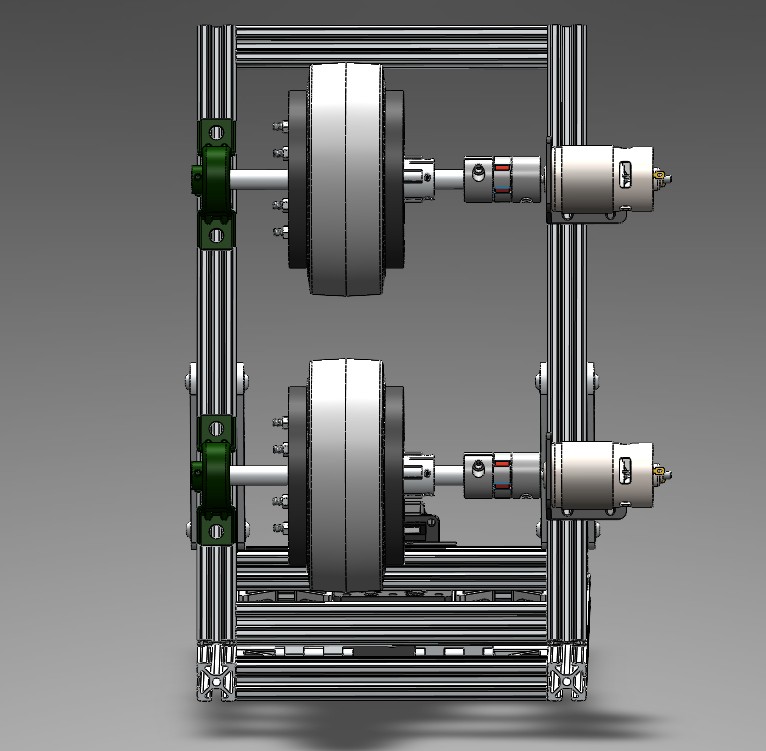
The old launcher used epoxy between hub and shaft and it failed under load. This one clamps instead. A 3D-printed plate sits on each face of the wheel with a lip that catches the contour of the wheel, and bolts run through both plates and the wheel to pull it all into one rigid unit.
The back plate bolts to a clamping hub, which set-screws onto a 1/2" steel shaft running through the bore of the wheel. A flexible coupling ties that shaft to the motor and a pillow block secures the other end, so the wheel is held at both ends instead of hanging off the motor bearings.
Self-locking tilt
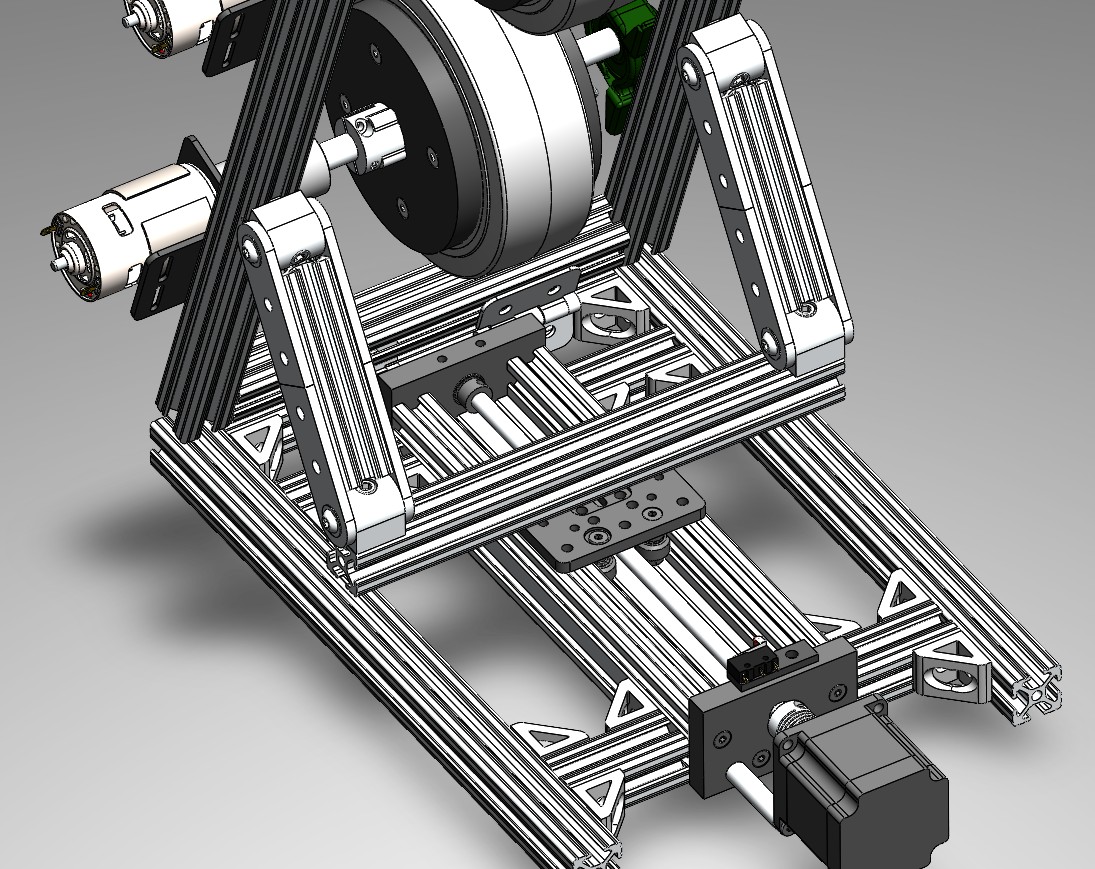
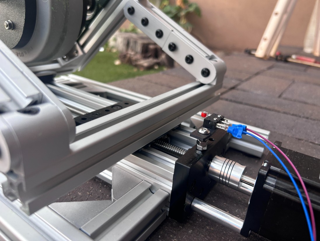
A linear actuator driven by a lead screw allows adjustable launch angle betwwen 5° to 45° via linkages and a hinge. A thread and brass anti-backlash nut resist backdriving enough to hold any angle with the stepper unpowered.
Link lengths and pivot positions came out of iterating in SolidWorks and checking the angle at multiple points along the length of travel.
Electronics enclosure
Everything sits on a removable backplate inside a sealed ABS box: ESP32, two BTS7960 drivers, the TB6600, the buck converter, the fuse block, and the voltage divider. Everything lifts out easily if changes need to be made.
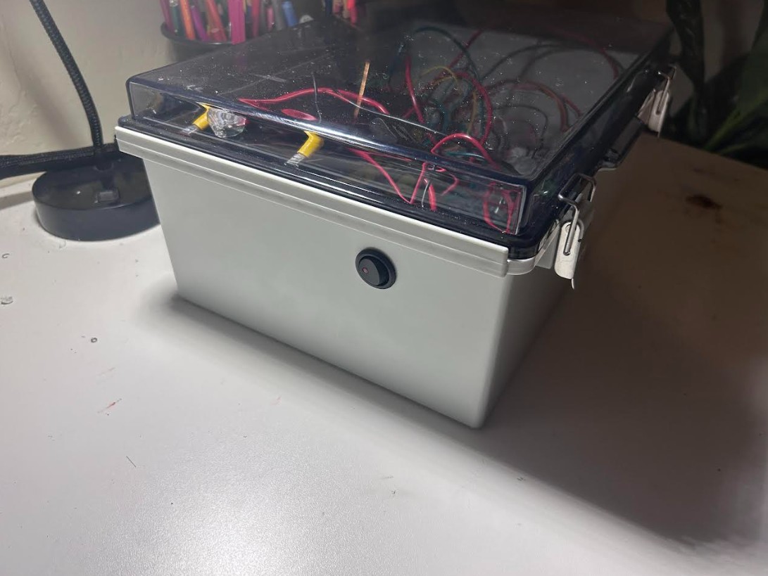
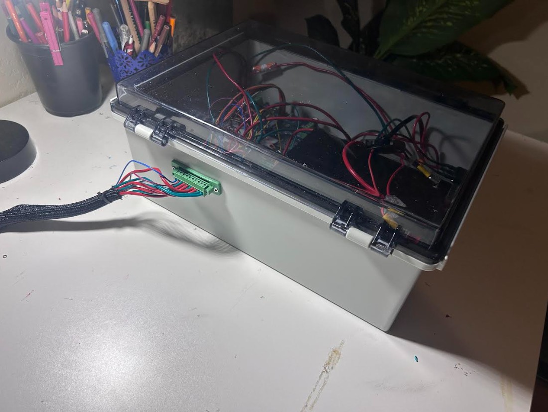
Only two things extrude through the wall of the box.
- Master switch. One 12V rocker on the outside. On powers the system, off powers it down.
- Panel-mount connector. A 10-pin screw terminal block with the flanged half fitted through a cut-out in the enclosure wall and bolted down. It carries power for both flywheel motors, the four stepper coil wires, and the limit switch. On the launcher side all ten wires route into the mating plug, so the harness pulls off in one piece.
Power and control
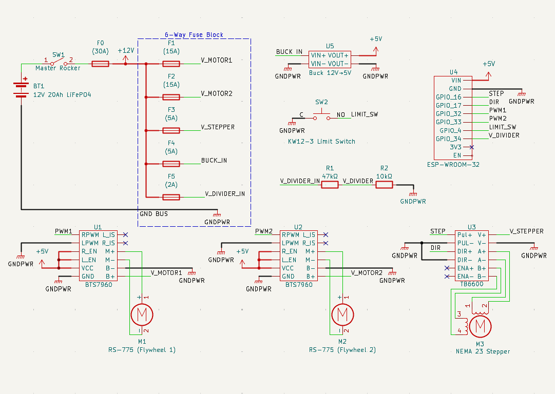
A 12V 20Ah LiFePO4 pack feeds a 6-channel fuse block behind a 30A main fuse and the master rocker: 15A to each flywheel driver, 5A to the stepper driver, 3A to the buck converter that powers the ESP32.
Everything grounds to the bus on the fuse block, so there is one ground reference. The only other input is a microswitch at the home end of the tilt, on a pulled-up GPIO.
Battery voltage runs through a 47k/10k divider into an ESP32 pin, which drops it into the 3.3V input range.
The whole system was drawn in KiCad and the schematic is what the build follows. The BTS7960, TB6600, buck converter, and ESP32 module are not in the stock libraries, so custom symbols were made for them.
Firmware and control app
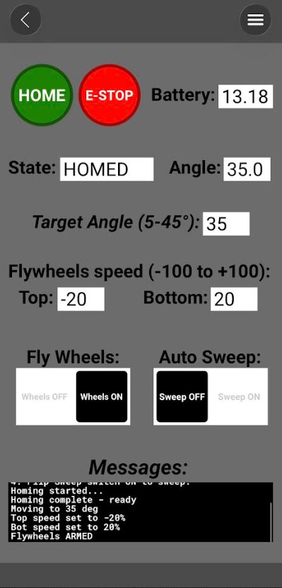
The launcher runs entirely from a phone over Bluetooth using RemoteXY, which binds app widgets straight to firmware variables.
Speeds get range-checked before they reach the drivers, sweep will not start unless the flywheels are armed with both speeds non-zero, and homing restricts every later angle command to the 5° to 45° sweep range.
The biggest changes to the firmware over the summer: replacing four sweep speed buttons with one on/off switch, restricting the sweep endpoints to a useful range instead of the full stroke, updating the UI during blocking homing loops, hard-braking at the limit switch, and adding battery monitoring.
What the app exposes:
- HOME. Runs the homing routine to establish the zero-angle reference.
- E-STOP. Disarms the flywheels and stops all motion immediately, and flips the ARM switch to match.
- Target angle. Takes 5 to 45 degrees and drives the actuator there. Anything outside that gets rejected with a note in the log.
- Wheel speeds. Top and bottom, -100 to +100 percent each. Negative runs the wheels backward.
- Flywheel ARM. Master enable. Wheels will not spin at any commanded speed until this is on, and it turns off if theres any error or E-STOP is pressed.
- Sweep. Oscillates the angle between 15° and 40° while the wheels spin. Refuses to start unless they are armed with speeds set.
- Live state. System state, current angle, battery voltage, and a scrolling terminal for status and errors.
Homing and safety
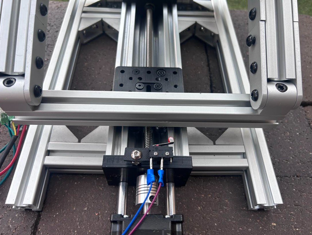
On startup the ESP32 walks the stepper slowly toward the microswitch, calls that spot zero, then backs off just enough to release it.
To keep it from coasting past, the routine jumps deceleration to 50,000 steps/s² the moment the switch trips.
Testing and results
- Range. 50% throttle at a 25° angle clears a full court, about 78 ft. Exit velocity was never measured directly, but that range implies 15 to 25 m/s.
- Consistency. RPM appeared to barely dropped between shots. Speeds stayed very consistent.
- Battery life. 60 to 90 minutes of active testing per charge. Idle time is basically unlimited since the motors are the only real draw.
- Reliability. After dropping stepper current from 2.8A to 1.5A for quieter, cooler running and rebalancing the flywheels with everything retorqued, it runs full sessions with no missed steps, dropped connections, or overheating.
The Bigger Picture
Still to come